Forced commutation are provided in the inverter circuit to extend the speed range from zero to base speed. The cost of the inverter increases due to forced commutation circuit. The machine is operated at UPF. Efficiency is improved and the drive can be used for low to medium range in CLM mode.
Among all drives possible with sychronous motor, LCI fed sychronous motor is popular in CLM mode. At low speeds the commutation should be assisted. We shall see some of the methods employed for starting and bringing the motor to a speed where the load commutation can take over. As the forced commutation circuitry is required only for low speed the size of the circuit is relatively small.
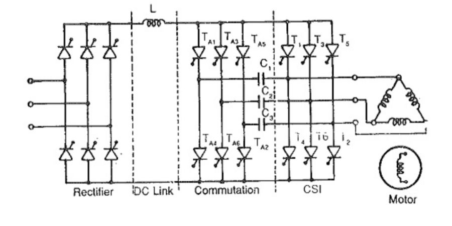
A CSI individual commutation is very commonly used and the motor may be operated at UPF. From it can be seen that, a large inductance is present in the dc link which makes the source current fed to inverter a constant hence it is a current source inverter. Here each main thyristor to provided with a auxiliary thyristor for commutation purpose.
Forced commutation qt low speed can also be obtained by means of a auxiliary thyristor at the fourth leg to the inverter. A commutating capacitor is connected across the star point and the common point of the two auriliary thyristors. At kow speeds the voltage across the capacitor is used for commutating the main thyristors. Once the machine achieves the speed where load commutation can take place, the fourth is cut off. This type of inverter is called as third harmonics commutated inverter.
A kind of artificial quenching is obtained in dc link current interruption at low speeds. The dc link current is controlled so that it goes from rectification to inversion. The rotor position sensor send information to the control unit of the machine side converter to block the firing pulses to the control unit of outgoing thyristor and provide to the incoming one. Due to the transition of the line side converter the polarity of the dc link voltage has xhanged. Consequently the dc link current decays to zero and maintainsfor a time greater than the turn off time of the thyristors. After this dead zone period the line side converter is again made as a rectifier. The dc link current builds up the current and flows through the new thyristors. Similar sequence of operation takes place in order commutations.
Candlemonk | Earn By Blogging | The Bloggers Social Network | Gamified Blogging Platform
Candlemonk is a reward-driven, gamified writing and blogging platform. Blog your ideas, thoughts, knowledge and stories. Candlemonk takes your words to a bigger audience around the globe, builds a follower base for you and aids in getting the recognition and appreciation you deserve. Monetize your words and earn from your passion to write.