Now a days more attention is being paid towards understanding the geste of the coetaneous motor fed from a VSI
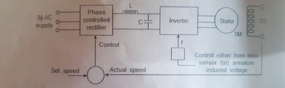
These drives as said eariler can be developed to have 1. tone control mode using a rotor position detector or from phase position of stator voltage.
2. Separate conteol mode, where the speed of the motor is determined by the external frequence grom a demitasse oscillator. This is the open circle control mode.
As bandied before when the motor is tone controlled it behaves like commutator less motor mode and has better stability characteristics. While it's separate controlled the motor has instqbility problems and hunting bahaviour analogous to a conventional coetaneous motor. A normal VSI with 180 degree conduction of thyristors requires forced dicker and cargo dicker isn't possible.
Three combinations are possible yo give a variable voltage variable frequence force to coetaneous motor fed from VSI
Forecourt surge inverter
b. PWM inverters
Chopper with square earthenware inverter
In all the case the SM can be operated either in separates or in tone controlled mode. All the below schemes are deputized
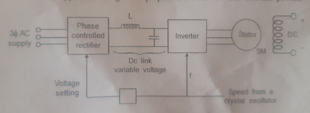
(a) SQUARE WAVE INVERTERS:
Here the dc link voltage is variable i.e the voltage control is obtained to the inverter using phase controlled rectifier. The disadvantage of this method is that the commutation is difficult at very low speeds. Hence it is applicable only for medium to high speed applications. Since the output voltage is a square wave, the inverter is called variable voltage inverter or square wave inverter.
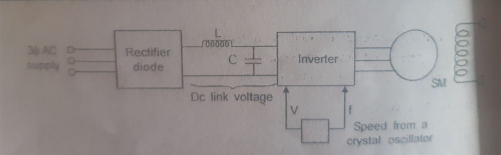
(b)PWM INVERTER:
The second methods is to have voltage conteol with the inverter itself using the principles of PWM. Here the dc link voltage is content. Here diode rectifier is used on the line side. It doesn't have difficulties in communication at low speeds. It has wide range of speed applications.
(c) CHOPPER WITH SQUARE WAVE INVERTER:
The third methods is to include a dc chopper in between the diode rectifier and the inverter. It has many advantage though it seems to the complex circuitry. Here 3 simple converter are used and it is possible to reduce the link inductance by having synchronous control of the chopper.
The output voltage of the inverter is non-sinusoidal hence the behaviour of the machine will be different from its conventional methods. We must know the steady state performance to determine the effect od non-sinusoidal waveforms on torque devwloped and machine losses harmonic content.