
INTRODUCTION
DC Motor speed can be controlled through DC chopper. Simple block diagram of DC chopper drives sysytem.
Fixed DC voltage is fed to the DC chopper circuit. DC chopper convert fixed DC into variable voltage. This variable DC voltage is fed to the motor. By varying the DC voltage the motor speed can be controlled. Self commutated devices such as MOSFETs, power transistors, IGBTs, GTOs and IGCTs are used for building choppers beause, they ca be operated at a higher frequency for the same rating.
ADVANTAGES OF DC CHOPPER CONTROL:
High efficiency
Flexibility in control
Light weight
Small size
Quick response
Regeneration down to very low speed
APPLICATION OF DC CHOPPER DRIVES:
Battery operated vehicles
Hoists
Teolley cars
Electric braking
Traction motor control in electric traction
TYPES OF DC CHOPPER DRIVES
First quadrant chopper or type A chopper
Second quadrant chopper or tye B chopper
Two quadrant type A chopper or type C chopper
Two quadrant type B chopper or type D type
Four quadrant chopper or type E chopper
FIRST QUADRANT OR TYPE A OR MOTORING CHOPPER:
In the past series motor was used in traction because it has high starting torque. It has number of limitations. The field of the motor cannot be controlled easily by static means.
If field control is not employed the series motor must be designed with its base speed equal to the higher desired speed of the drives. The higher base speed are obtained using fewer turns in the field windings.
This reduces the torque per ampere at zero and low speed. Presently separately excited motor are aslo used in traction. Because of limitations of a series motor separated excited motor are now preferred even for traction applications.
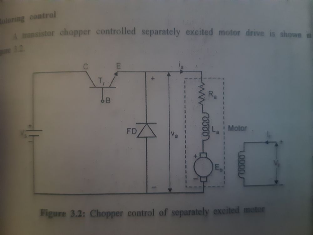
MOTORING CONTROL
A trasistor chopper controlled separated excited motor drives

Current limit control is used in chopper. In current limit control, the load current is allowed to vary between two given limits. The ON and OFF times of the chopper adjust automatically. When the current increases beyond the upper limit the chopper is tuned off. The load current is tuned ON. The current starts increasing in the load. The load current and voltage waveform. By assuming proper limit of current the amplitude of the ripple can be controlled.
The lower the ripple current, the higher the chopper frequency. By this switching losses get increased. Discontinuous conduction is avoided in this case. The current limit control is superior one.


