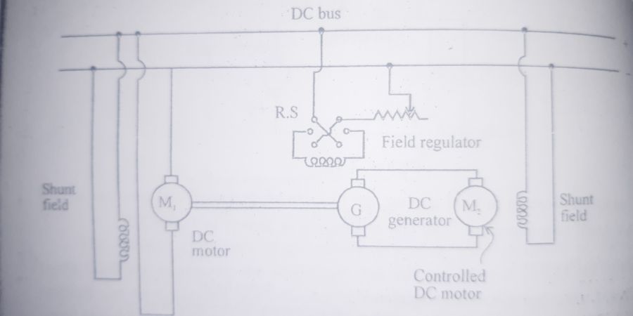

The ward-loenard speed control system. This system was introduced in the 1890s, and was a significant step in the evolution of dc drives. This system is mainly for used very sensitive speed control and is required for electric exclators, elevator, colliery winders and the main drives in steel mills and paper mills.
It consists of three dc machines i.e, two dc motor and one dc generator. The system uses a motor generator (M1-G) set to power the dc drive motor. M1 is the main motor and is directly coupled to the dc generator G. DC supply is given to the armature terminal as wall as shunt field winding. The M-G set runs at constant speed. The voltage of the generator can be varied is fed to the controlled dc motor(M2)
The controlled dc motor M2 rotation can be reersing the direction ca be changed by reversing the direction of the field current of generator G. It is done by using reversing switch S and the generated voltage can be reversed nd the motor rotates direction.
In this method speed conteol is combined by armature control and flux control. The armature voltage control can be achieved by varying the field of dc generator. The flux control method can be achieved by varying the field of the controlled dc motor. The dc motor speed ca ne controlled through power semiconductor switches. Here, the power semiconductor switches are SCR, MOSFET,IGBT etc. This type of speed control is called ward-leonard drive. The ward-leanard system provides a constant torque as well as constant horse power drive . In armature voltage control at full field, T alpha Ia consequently, the maximum torque that the machine can deliver has a constant value. In the field control at rated armature voltage, Pm alpha Ia. Therefore maximum power developed by the motor has a constant value
ADVANTAGES
The advantage of this methods are:


