
CLOSE LOOP CONTROL OF ELECTRICAL DRIVE
Feedback loops in an electrical drives may be provided to satify one or more of the following requirements.
Protection
Improvement of speed response
To improve steady state accuracy
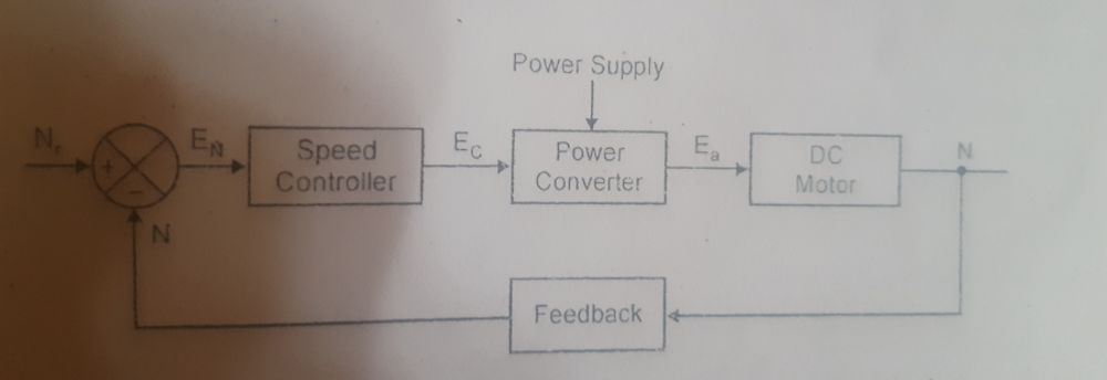
Basic block diagram of a closed loop control system of dc motor. This system consists of dc motor, power converter feedback path, comparator and speed controller.

Here, the motor speed can be sensed by speed sensor. It is a feedback signal N i.e, actual speed. Actual speed is compared with reference signal Nf. The error signal En is goes to the speed controller. Speed controller produces control signal or control voltage Ec. This control signal is fed to the power converter. The power converter output can be changed according to the control signal. By changing the output voltage, motor speed ca be controlled. This section describes various closed loop configuration which find application in electric drives.
CURRENT LIMIT CONTROL:
 Current limit control scheme of is employed to limit the motor and motor current below a safe limit during flash operation. It has a current feedback circle with a threshold sense ciruit. As long as the current is within a set maximum value, feedback circle doesn't affect operation of the drives. During a flash operation, if current exceed the set maximum value, feedback circle becomes active and current is forced below the set maximum value, which causes the feedback circle to come inactive again.
CLOSED LOOP TORQUE CONTROL:

Closed Circle necklace control scheme of discoveries operation in battery operated vehicles and electrical trains. motorist press the accelerator to set necklace referenceT. Through closed circle control of necklace the factual motor necklace T follow necklace referenceT. Speed feedback circle is present through the motorist.
CLOSED LOOP SPEED CONTROL:
A closed loop speed control scheme which is widely uses in electrical drives. It employs an inner current control within an outer speed loop. Inner current control loop is peovided to limit the converter and motor current or motor torque below a safe limit.

Drives of operation as follows an increase in reference speed produce a positive error. Speed is processed through a speed controller and applied to a current limiter which saturates even for a small speed error consequently limiter sets current reference for inner current control loop at a value corresponding to the maximum allowable current.
When close to the desired speed limiter desaturates. Steady state is reached at the desired speed and at current for which motor torque is equal to the load torque.
